sábado, 21 de abril de 2012

Encaminamiento Multicast


"Una revisión rápida de algunos de los protocolos de
encaminamiento dinámico de tráfico multicast

El motivo de la utilización de multicast es bastante obvio, pero a la hora de diseñar una solución de encaminamiento multicast escalable que se adapte a las necesidades reales es difícil elegir cuál es la mejor arquitectura de las posibles, por ello se van a repasar algunas de las opciones.

Métodos multicast

Existen dos modelos de cursar el tráfico multicast:

  •  Anycast Source Multicast (ASM): Este es el modelo multicast “tradicional”, en el que se tienen varios orígenes multicast dentro de un mismo grupo multicast.
  •  Source Specific Multicast (SSM): Por el contrario a ASM, en el nuevo modelo SSM el receptor (receiver) puede seleccionar el origen multicast, mejorando la eficiencia en la red y aumentando la seguridad. Para realizar esta selección, el receptor debe valerse de la última versión IGMP, el protocolo IGMPv3.

  
Esquemas de enrutamiento multicast ASM

Aquí se van a discutir algunos de los protocolos utilizados para solventan la problemática de direccionar tráfico multicast según el modelo ASM:

  •  Esquema "Source-tree"
La idea es sencilla, inicialmente los orígenes envían los datos en todas las direcciones posibles y son los routers quien deciden si ese flujo debe ser recibido o no (lo que es llamado pruning) según las peticiones IGMP de los diferentes receivers. 


Debido a que este comportamiento envía el tráfico multicast en todas las direcciones, es muy posible que los routers reciban el mismo flujo por varias interfaces. Para solventar esto el router rechaza todo tráfico que no sea recibido por la interfaz que utilizaría al enviar tráfico unicast al origen del tráfico multicast.
           
Dos protocolos que utilizan esta técnica son:

o    Distance Vector Multicast Routing Protocol (DVMRP)
o    Protocol Independent Multicast Dense-Mode (PIM-DM)

Estos protocolos son similares, con la salvedad de que el primero (más antiguo) utiliza una tabla de enrutamiento destinada solo al tráfico multicast, mientras que PIM-DM se vale de la tabla de enrutamiento unicast.

  • Esquema “Shared-tree"
Esta arquitectura redistribuye la información de enrutamiento mediante la centralización de esta en uno de los routers de la topología. Esto genera otra serie de puntos de diseño, como es la redistribución de rutas entre estos routers así como la prestación de alta disponibilidad del servicio que ofrecen.

Algunos de los protocolos que se pueden englobar en esta clasificación son:

o    Core-Based Tree (CBT)
o    Protocol Independent Multicast Sparce-Mode (PIM-SM)
o    Bidirectional Protocol Independent Multicast (Bidir-PIM)


Comparativa de protocolos Shared-tree

Existen diferencias de funcionamiento entre los protocolos shared-tree mencionados antes:

  •  Core-Based Tree (CBT)

    El router que centraliza las rutas es llamado “Core”.  Cuando el origen de datos multicast comienza a transmitir, su router local reenviará dicho tráfico hasta este router Core.

    Cuando el receiver se une a un grupo multicast el router de su segmento de red direcciona el mensaje de Join hacia el router Core. Ese mismo camino es el que seguirá el flujo de datos Multicast ya       que el router Core centralizará no solo las tablas de enrutamiento, si no también el tráfico multicast.

    Este comportamiento tiene el inconveniente de que es muy posible que, a no ser que el router Core se encuentre muy cerca del origen del tráfico multicast, las rutas entre el origen y el receiver no sean las óptimas, como se puede ver en este ejemplo encontrado en http://www.cl.cam.ac.uk/~jac22/books/mm/book/node78.html


           Ilustración 1 – Rutas no optimas con CBT 


  • Protocol Independent Multicast Sparce-Mode (PIM-SM)
Este protocolo solventa el problema de que el tráfico multicast esté obligado a transcurrir por el router Core (en PIM-SM se denomina Rendezvous Point (RP) ), de tal manera que si la ruta que pasa a través del RP no es la optima no será la utilizada.

Los RP utilizan el modelo source-tree para llegar a los orígenes multicast pero, cada router cliente  genera lo que se llaman unidirectional trees gracias a los mensajes de Join de los receivers. Estos caminos son utilizados en el momento en que se detecta que son mejores que el utilizado por el RP.

Dicho procedimiento viene bien reflejado en el siguiente esquema que aparece en http://www.cisco.com/web/about/ac123/ac147/ac174/ac198/about_cisco_ipj_archive_article09186a00800c851e.html
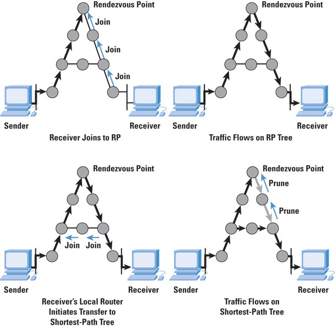


Ilustración 2 – Elección del camino óptimo en PIM-SM 

En la configuración del RP se pueden optar por dos opciones, configurar los RP manualmente en todos los routers o utilizar alguno de los métodos de auto descubrimiento: Auto-RP y BSR, siendo el primero de ellos el que más versatilidad proporciona, ya que en el es posible la modificación de parámetros (como los temporizadores) y puede ser utilizado en el modo híbrido también llamado "PIM-sparse-dense mode".

Al ser el RP un punto crítico en la arquitectura PIM-SM, es necesario proporcionar algún método de redundancia. La alta disponibilidad del RP se consigue utilizando más de un RP al mismo tiempo (Anycast-RP) y gestionar su utilización mediante el protocolo Multicast Source Discovery Protocol (MSDP). Este protocolo permite que los RP compartan información sobre el estado de los orígenes multicast.

MSDP también es utilizado cuando, por causas de escalabilidad, o por la existencia de varios dominios de gestión (por ejemplo varios ISPs), se hace necesaria la creación de múltiples "dominios" o "zonas" multicast, los cuales pueden ser regidos por diferentes RPs. Estos dominios necesitan el protocolo MSDP para poder comunicarse los orígenes que residen en cada uno de ellos respectivamente.


  • Bidirectional Protocol Independent Multicast (Bidir-PIM)

El protocolo Bidir-PIM está basado en PIM-SM pero con algunas diferencias. PIM-SM utiliza el RP (Rendez-Vous Point) para gestionar el envío de datos a cada uno de los grupos multicast mediante el shared-tree desde los RP hasta los receptores (recivers o clientes) y source-tree desde el origen hasta el RP. Esto puede llegar a ser un problema si se tiene un alto número de orígenes, ya que puede llegar a sobrecargar la máquina RP.

En el protocolo Bidirectional PIM no existe el source-tree entre el origen y el RP, si no que esta comunicación se realiza mediante un shared-tree lo que lo hace un protocolo muy escalable en cuanto al número de orígenes multicast se refiere.

La mayor escalabilidad se gana a costa de que todo el tráfico se dirige hacia el RP. Esto hace que exista posibilidad de conmutar a una ruta obtenida por source-tree (como sucedía en PIM-SM).
Debido a que este protocolo solo utiliza shared-trees necesita un método adicional para enviar el tráfico hasta el RP. El método consiste en disponer un nuevo rol, el Designated Forwarder (DF), el cual decide los paquetes que tienen que ser enviados hacia el RP.

Este protocolo tiene el nombre de bidireccional ya que tiene la peculiaridad de que las redes de los orígenes de tráfico también pueden ser receptores, lo que puede ser necesario en algún diseño en el que existan aplicaciones que requieran muchos orígenes y muchos destinos simultáneamente.

Este comportamiento bidireccional conlleva que el protocolo Reverse Path Forwarding (RPF) no puede ser utilizado conjuntamente con este protocolo, ya que se utiliza un mismo shared-tree para llevar el tráfico desde el origen al RP como el tráfico desde el RP a los recivers.

En la siguiente imagen se muestran las diferencias entre Source-tree, Shared-tree y Bidir-PIM. En el último caso existen dos orígenes (S1 y S2) y se observa como se crea un camino bidireccional: 


Ilustración 3 – Diferencias entre Source-tree, Shared-tree y Bidir-PIM 

Al igual que en PIM-SM, en Bidir-PIM el RP también es un punto crítico (incluso más en este último caso) que aporta un servicio que debe ser redundado. En este caso no se puede utilizar la misma metodología que con PIM-SM, ya que no pueden utilizarse varios RP a la vez, como se hacía con Anycast-RP, debido a que no utiliza un source-tree para la comunicación con el origen y todo el tráfico fluirá por el RP. En el caso de Bidir-PIM se hace uso del llamado Phantom-RP, un procedimiento parecido al VRRP o HSRP en el que se crea una "instancia virtual del RP".

Esquemas de enrutamiento multicast SSM


El protocolo que se basa en el esquema SSM es el llamado Protocol Independent Multicast-Source-Specific Multicast mode (PIM-SSM) el cual hace uso de la lógica SSM mediante la cual un grupo multicast ya no está solo definido por un grupo de receptores, si no que también lo está por el origen al que quieren vincularse.

Este protocolo está pensado para arquitecturas uno-a-muchos y puede verse como una modificación del protocolo PIM-SM, aunque tiene una gran diferencia, y es que PIM-SSM no hace uso de los RPs, ya que se conoce el origen multicast de antemano (al haber sido elegido explícitamente por el receptor), siendo el camino elegido mediante el protocolo de direccionamiento unicast.


sábado, 31 de marzo de 2012

SNMP MIBs y traps comunes en Radware Alteon

"En esta entrada incluyo algunos traps SNMP y OIDs que pueden ser configurados en la monitorización de los dispostivos Radware Alteon, separados en dos tablas."

Algunos OIDs de la versión AlteonOS 28:

Nombre
OID
Descripción
CPU
cpuUtil1Second
1.3.6.1.4.1.1872.2.5.1.2.2.1.0
The percentage of CPU utilization as measured over the last one second interval.
cpuUtil4Seconds
1.3.6.1.4.1.1872.2.5.1.2.2.2.0
The percentage of CPU utilization as measured over the last four second interval.
cpuUtil64Seconds
1.3.6.1.4.1.1872.2.5.1.2.2.3.0
The percentage of CPU utilization as measured over the last 64 second interval.
Port Stats
portStatsTable
1.3.6.1.4.1.1872.2.5.1.2.3.1
The table of port statistics.
portStatsIndx
1.3.6.1.4.1.1872.2.5.1.2.3.1.1.1
The port index
portStatsPhyIfOutNUcastPkts           
1.3.6.1.4.1.1872.2.5.1.2.3.1.1.10
The total number of packets that higher-level protocols requested be transmitted to a non-unicast (i.e., a subnetwork-broadcast or subnetwork-multicast) address, including those
that were discarded or not sent.
portStatsPhyIfOutDiscards  
1.3.6.1.4.1.1872.2.5.1.2.3.1.1.11
The number of outbound packets which were chosen to be discarded even though no errors had been detected to prevent their being transmitted. One possible reason for discarding  such a packet could be to free up buffer space.
portStatsPhyIfOutErrors     
1.3.6.1.4.1.1872.2.5.1.2.3.1.1.12
The number of outbound packets that could not be transmitted because of errors.
portStatsPhyIfOutQLen      
1.3.6.1.4.1.1872.2.5.1.2.3.1.1.13
The length of the output packet queue (in packets)
portStatsPhyIfInBroadcastPkts           
1.3.6.1.4.1.1872.2.5.1.2.3.1.1.14
The number of packets, delivered by this sub-layer to a higher (sub-)layer, which were addressed to a broadcast address at this sub-layer.
portStatsPhyIfOutBroadcastPkts           
1.3.6.1.4.1.1872.2.5.1.2.3.1.1.15
The total number of packets that higher-level protocols requested be transmitted, and which were addressed to a broadcast address at this sub-layer including those that were discarded or not sent.
portStatsPhyIfInOctets       
1.3.6.1.4.1.1872.2.5.1.2.3.1.1.2
The total number of octets received on the  interface, including framing characters.
portStatsPhyIfInUcastPkts   
1.3.6.1.4.1.1872.2.5.1.2.3.1.1.3
The number of subnetwork-unicast packets delivered to a higher-layer protocol.
portStatsPhyIfInNUcastPkts 
1.3.6.1.4.1.1872.2.5.1.2.3.1.1.4
The number of non-unicast (i.e., subnetwork-broadcast or subnetwork-multicast) packets delivered to a higher-layer protocol.
portStatsPhyIfInDiscards    
1.3.6.1.4.1.1872.2.5.1.2.3.1.1.5
The number of inbound packets which were chosen to be discarded even though no errors had been detected to prevent their being deliverable to a higher-layer protocol. One possible reason for discarding such a packet could be to free up buffer space.
portStatsPhyIfInErrors        
1.3.6.1.4.1.1872.2.5.1.2.3.1.1.6
The number of inbound packets that contained errors preventing them from being deliverable to a higher-layer protocol
portStatsPhyIfInUnknownProtos           
1.3.6.1.4.1.1872.2.5.1.2.3.1.1.7
The number of packets received via the interface which were discarded because of an unknown or unsupported protocol.
portStatsPhyIfOutOctets     
1.3.6.1.4.1.1872.2.5.1.2.3.1.1.8
The total number of octets transmitted out of the interface, including framing characters.
portStatsPhyIfOutUcastPkts 
1.3.6.1.4.1.1872.2.5.1.2.3.1.1.9
The total number of packets that higher-level protocols requested be transmitted to a subnetwork-unicast address, including those that were discarded or not sent.
TCP Packets
ipInReceives       
1.3.6.1.2.1.4.3
The total number of input datagrams received from interfaces, including those received in error
ipInHdrErrors      
1.3.6.1.2.1.4.4
The number of input datagrams discarded due to errors in their IP headers, including bad checksums, version number mismatch, other format errors, time-to-live exceeded, errors discovered in processing their IP options, etc.
ipInAddrErrors    
1.3.6.1.2.1.4.5
The number of input datagrams discarded because the IP address in their IP header's destination field was not a valid address to be received at this entity. This count includes invalid addresses (e.g., 0.0.0.0) and addresses of unsupported Classes (e.g., Class E). For entities which are not IP Gateways and therefore do not forward datagrams, this counter includes datagrams discarded because the destination address was not a local address.
ipForwDatagrams
1.3.6.1.2.1.4.6
The number of input datagrams for which this entity was not their final IP destination, as a result of which an attempt was made to find a route to forward them to that final destination.
In entities which do not act as IP Gateways, this counter will include only those packets which were Source-Routed via this entity, and the Source-Route option processing was successful.
ipInUnknownProtos
1.3.6.1.2.1.4.7
The number of locally-addressed datagrams received successfully but discarded because of an unknown or unsupported protocol.
ipInDiscards       
1.3.6.1.2.1.4.8
The number of input IP datagrams for which no problems were encountered to prevent their continued processing, but which were discarded (e.g., for lack of buffer space). Note that this
counter does not include any datagrams discarded while awaiting re-assembly
ipInDelivers        
1.3.6.1.2.1.4.9
The total number of input datagrams successfully delivered to IP user-protocols (including ICMP).
ipOutRequests     
1.3.6.1.2.1.4.10
The total number of IP datagrams which local IP user-protocols (including ICMP) supplied to IP in requests for transmission. Note that this counter does not include any datagrams  counted in ipForwDatagrams.
ipOutDiscards     
1.3.6.1.2.1.4.11
The number of output IP datagrams for which no problem was encountered to prevent their transmission to their destination, but which were discarded (e.g., for lack of buffer space). Note that this counter would include datagrams counted
in ipForwDatagrams if any such packets met this (discretionary) discard criterion
ipOutNoRoutes   
1.3.6.1.2.1.4.12
The number of IP datagrams discarded because no route could be found to transmit them to their destination. Note that this counter includes any packets counted in ipForwDatagrams which meet this 'no-route' criterion. Note that this includes any
datagarms which a host cannot route because all of its default gateways are down
ipReasmTimeout  
1.3.6.1.2.1.4.13
The maximum number of seconds which received fragments are held while they are awaiting reassembly at this entity.
ipReasmReqds    
1.3.6.1.2.1.4.14
The number of IP fragments received which needed to be reassembled at this entity
ipReasmOKs       
1.3.6.1.2.1.4.15
The number of IP datagrams successfully re-assembled
ipReasmFails      
1.3.6.1.2.1.4.16
The number of failures detected by the IP re-assembly algorithm (for whatever reason: timed out, errors, etc). Note that this is not necessarily a count of discarded IP fragments
since some algorithms (notably the algorithm in RFC 815) can lose track of the number of fragments by combining them as they are received.
ipFragOKs         
1.3.6.1.2.1.4.17
The number of IP datagrams that have been successfully fragmented at this entity
ipFragFails         
1.3.6.1.2.1.4.18
The number of IP datagrams that have been discarded because they needed to be fragmented at this entity but could not be, e.g., because their Don't Fragment flag was set
ipFragCreates     
1.3.6.1.2.1.4.19
The number of IP datagram fragments that have been generated as a result of fragmentation at this entity.
UDP Packets
udpInDatagrams  
1.3.6.1.2.1.7.1
The total number of UDP datagrams delivered to UDP users
udpNoPorts        
1.3.6.1.2.1.7.2
The total number of received UDP datagrams for which there was no application at the destination port.
udpInErrors        
1.3.6.1.2.1.7.3
The number of received UDP datagrams that could not be delivered for reasons other than the lack of an application at the destination port.
udpOutDatagrams
1.3.6.1.2.1.7.4
The total number of UDP datagrams sent from this entity
Real Servers
slbStatRServerTable
.1.3.6.1.4.1.1872.2.1.8.2.5 
The real server statistics table
slbStatRServerEntry
.1.3.6.1.4.1.1872.2.1.8.2.5.1 
The statistics of a particular real server
slbStatRServerIndex
.1.3.6.1.4.1.1872.2.1.8.2.5.1.1 
The real server number that identifies the server.
slbStatRServerCurrSessions
.1.3.6.1.4.1.1872.2.1.8.2.5.1.2 
The number of sessions that are currently handled by
the real server.
slbStatRServerTotalSessions
.1.3.6.1.4.1.1872.2.1.8.2.5.1.3 
The total number of sessions that are handled by the
real server
slbStatRServerFailures
.1.3.6.1.4.1.1872.2.1.8.2.5.1.4 
The total number of times that the real server is
claimed down
slbStatRServerHighestSessions
.1.3.6.1.4.1.1872.2.1.8.2.5.1.5 
The highest sessions that have been handled by the real
server.
slbStatRServerHCOctets
.1.3.6.1.4.1.1872.2.1.8.2.5.1.6 
The total number of octets received and transmitted out
of the real server
slbStatRServerHCOctetsLow32
.1.3.6.1.4.1.1872.2.1.8.2.5.1.7 
The total number of octets received and transmitted out
of the real server
slbStatRServerHCOctetsHigh32
.1.3.6.1.4.1.1872.2.1.8.2.5.1.8 
The higher 32 bit value of octets received and transmitted out
of the real server.
Virtual Servers
slbStatVServerTable
.1.3.6.1.4.1.1872.2.1.8.2.7            
The virtual server statistics table.
slbStatVServerEntry
.1.3.6.1.4.1.1872.2.1.8.2.7.1            
The statistics of a particular virtual server group.
slbStatVServerIndex
.1.3.6.1.4.1.1872.2.1.8.2.7.1.1 
The virtual server number that identifies the server.
slbStatVServerCurrSessions
.1.3.6.1.4.1.1872.2.1.8.2.7.1.2 
The number of sessions that are currently handled by
the virtual server.
slbStatVServerTotalSessions
.1.3.6.1.4.1.1872.2.1.8.2.7.1.3 
The total number of sessions that are handled by the
virtual server
slbStatVServerHighestSessions
.1.3.6.1.4.1.1872.2.1.8.2.7.1.4 
The total number of times that the virtual server is
claimed down
slbStatVServerHCOctets
.1.3.6.1.4.1.1872.2.1.8.2.7.1.5 
The total number of octets received and transmitted out
of the virtual server
slbStatVServerHCOctetsLow32
.1.3.6.1.4.1.1872.2.1.8.2.7.1.6 
The total number of octets received and transmitted out
of the virtual server
slbStatVServerHCOctetsHigh32
.1.3.6.1.4.1.1872.2.1.8.2.7.1.7 
The higher 32 bit value of octets received and transmitted out
of the virtual server.
slbStatVServerHeaderHits
.1.3.6.1.4.1.1872.2.1.8.2.7.1.8 
The current HTTP header hits.
slbStatVServerHeaderMisses
.1.3.6.1.4.1.1872.2.1.8.2.7.1.9             
The current HTTP header misses
slbStatVServerHeaderTotalSessions
.1.3.6.1.4.1.1872.2.1.8.2.7.1.10 
The current HTTP total sessions
DNS
dnsSlbStatTCPQueries                  
1.3.6.1.4.1.1872.2.5.4.2.13.1
Total number of TCP DNS queries.
dnsSlbStatUDPQueries                  
1.3.6.1.4.1.1872.2.5.4.2.13.2
Total number of UDP DNS queries
dnsSlbStatInvalidQueries   
1.3.6.1.4.1.1872.2.5.4.2.13.3
Total number of UDP invalid DNS queries
dnsSlbStatMultipleQueries 
1.3.6.1.4.1.1872.2.5.4.2.13.4
Total number of UDP DNS multiple queries
dnsSlbStatDnameParseErrors           
1.3.6.1.4.1.1872.2.5.4.2.13.5
Total number of UDP DNS name parse errors
dnsSlbStatFailedMatches  
1.3.6.1.4.1.1872.2.5.4.2.13.6
Total number of UDP DNS failed matches
dnsSlbStatInternalErrors    
1.3.6.1.4.1.1872.2.5.4.2.13.7
Total number of DNS parsing internal errors


Y algunos traps interesantes:

Nombre
   OID
Descripción
linkUp
1.3.6.1.6.3.1.1.5.4
A linkUp trap signifies that the SNMPv2 entity, acting in an agent role, has detected that the ifOperStatus object for one of its communication links has transitioned out of the down state.
linkDown
1.3.6.1.6.3.1.1.5.3
A linkDown trap signifies that the SNMPv2 entity, acting in an agent role, has detected that the ifOperStatus object for one of its communication links  is about to transition into the down state.
altSwSlbRealServerUp
1.3.6.1.4.1.1872.2.5.7.6
A altSwSlbRealServerUp trap signifies that the real server (which had gone down )is back up and operational now. slbCurCfgRealServerIndex is the affected Real Server Number. The range is from 1 to slbRealServerMaxSize. slbCurCfgRealServerIpAddr is the IP address of the affected Real Server.  slbCurCfgRealServerName is the optional Name given to the affected Real Server.
altSwSlbRealServerDown
1.3.6.1.4.1.1872.2.5.7.7
A altSwSlbRealServerDown trap signifies that the real server has gone down and is out of service. slbCurCfgRealServerIndex is the affected Real Server Number. The range is from 1 to slbRealServerMaxSize. slbCurCfgRealServerIpAddr is the IP address of the affected Real Server. slbCurCfgRealServerName is the optional Name given to the affected Real Server.
altSwSlbRealServerServiceUp
1.3.6.1.4.1.1872.2.5.7.14
A altSwSlbRealServerServiceUp trap signifies that the service port of the real server is up and operational. slbCurCfgRealServerIndex is the affected Real Server Number. The range is from 1 to the value return from slbRealServerMaxSize. slbCurCfgRealServerIpAddr is the IP address of the affected Real Server. slbCurCfgRealServerName is the optional Name given to the affected Real Server. slbCurCfgVirtualServiceRealPort referenced in slbCurCfgVirtServicesTable. This is the layer 4 real port number of  the service.
altSwSlbRealServerServiceDown
1.3.6.1.4.1.1872.2.5.7.15
A altSwSlbRealServerServiceDown trap signifies that the service port of the real server is down and out of service. slbCurCfgRealServerIndex is the affected Real Server Number. The range is from 1 to the value return from slbRealServerMaxSize. slbCurCfgRealServerIpAddr is the IP address of the affected Real Server. slbCurCfgRealServerName is the optional Name given to the affected Real Server. slbCurCfgVirtualServiceRealPort referenced in slbCurCfgVirtServicesTable. This is the layer 4 real port number of the service.
altSwSlbRealServerOperEna
1.3.6.1.4.1.1872.2.5.7.34
A altSwSlbRealServerOperEna trap signifies that the real server is enabled operationally. The real server will be send traffic again. slbCurCfgRealServerIndex is the affected real server number. The range is from 1 to slbRealServerMaxSize. slbCurCfgRealServerIpAddr is the IP address of the affected real server. slbCurCfgRealServerName is the optional name given to the affected real server.
altSwSlbRealServerOperDis
1.3.6.1.4.1.1872.2.5.7.33
A altSwSlbRealServerOperDis trap signifies that the real server is disabled operationally. The real server will not be sent any traffic from the switch until the real server enabled operationally. slbCurCfgRealServerIndex is the affected real server number. The range is from 1 to slbRealServerMaxSize. slbCurCfgRealServerIpAddr is the IP address of the affected real server. slbCurCfgRealServerName is the optional name given to the affected real server.
altSwSlbVirtServerServicesUp
1.3.6.1.4.1.1872.2.5.7.25
A altSwSlbVirtServerServicesUp trap signifies that the service ports of the virtual server is up and operational. slbCurCfgVirtServerIndex is the affected Virtual Server Number. The range is from 1 to the value return from slbVirtServerTableMaxSize. slbCurCfgVirtServerIpAddress is the IP address of the affected Virtual Server. slbCurCfgVirtServerVname is the optional Name given to the affected Virtal Server.
altSwSlbVirtServerServicesDown
1.3.6.1.4.1.1872.2.5.7.26
A altSwSlbVirtServerServicesDown trap signifies that the service ports of the Virtual server is down and out of service. slbCurCfgVirtServerIndex is the affected Virtual Server Number. The range is from 1 to the value return from slbVirtServerTableMaxSize. slbCurCfgVirtServerIpAddress is the IP address of the affected Virtual Server. slbCurCfgVirtServerVname is the optional Name given to the affected Virtual Server.
altSwVrrpNewMaster
1.3.6.1.4.1.1872.2.5.7.16
The altSwVrrpNewMaster trap indicates that the sending agent has transitioned to 'Master' state. vrrpCurCfgVirtRtrIndx is the VRRP virtual router table index referenced in vrrpCurCfgVirtRtrTable. The range is from 1 to vrrpVirtRtrTableMaxSize. vrrpCurCfgVirtRtrAddr is the VRRP virtual router IP address.
altSwVrrpNewBackup
1.3.6.1.4.1.1872.2.5.7.17
The altSwVrrpNewBackup trap indicates that the sending agent has transitioned to 'Backup' state. vrrpCurCfgVirtRtrIndx is the VRRP virtual router table index referenced in vrrpCurCfgVirtRtrTable. The range is from 1 to vrrpVirtRtrTableMaxSize. vrrpCurCfgVirtRtrAddr is the VRRP virtual router IP address.
altSwDeviceTemperatureNormal
1.3.6.1.4.1.1872.2.5.7.40
Sent whenever the temperature changes back to normal.
altSwDeviceTemperatureHigh
1.3.6.1.4.1.1872.2.5.7.41
Sent whenever the temperature changes to high.
altSwDeviceTemperatureCritical
1.3.6.1.4.1.1872.2.5.7.42
Sent whenever the temperature becomes critical.
altSwTempExceedThreshold
1.3.6.1.4.1.1872.2.5.7.22
A altSwTempExceedThreshold trap signifies that the switch temperature has exceeded maximum safety limits. altSwTrapDisplayString specifies the sensor, the current sensor temperature and the threshold for the particular sensor.
altSwDualPowerSupplyUp
1.3.6.1.4.1.1872.2.5.7.44
This info trap is sent when a power supply changes state from inactive to active on a dual power supply device.
altSwDualPowerSupplyProblem
1.3.6.1.4.1.1872.2.5.7.43
This warning trap is sent when a power supply becomes inactive on a dual power supply device.
altSwPrimaryPowerSupplyFailure
1.3.6.1.4.1.1872.2.5.7.1
A altSwPrimaryPowerSupplyFailure trap signifies that the primary power supply failed.
altSwTputReachThreshold
1.3.6.1.4.1.1872.2.5.7.47
Sent whenever the throughput reaches threshold value.
altSwTputExceedLimit
1.3.6.1.4.1.1872.2.5.7.48
Sent whenever the throughput exceeds threshold value.
altSwcacheBelow80
1.3.6.1.4.1.1872.2.5.7.55
Allocated cache space is below 80%
altSwcacheReache80
1.3.6.1.4.1.1872.2.5.7.54
Allocated cache space has reached 80%.
altSwcacheLimitShortSpace
1.3.6.1.4.1.1872.2.5.7.53
Temporarily limiting caching due to critical cache space shortage.
altSwcpuFell80
1.3.6.1.4.1.1872.2.5.7.58
CPU utilization has dropped below 80%, while before that it was above 80%.
altSwcpuCross80
1.3.6.1.4.1.1872.2.5.7.57
CPU utilization has reached 80%, while before that it was below 80%
altSwlogDiskSpace
1.3.6.1.4.1.1872.2.5.7.56
80% of logging disk space was reached.
altSwSlbRealServerMaxConnReached
1.3.6.1.4.1.1872.2.5.7.8
A altSwSlbRealServerMaxConnReached trap signifies that the real server has reached maximum connections. The Real server will not be sent any more traffic from the switch until the number of connections drops below the maximum. If a backup server has been specified, it will be used to service additional requests, which is referred to as an Overflow server. slbCurCfgRealServerIndex is the affected Real Server Number. The range is from 1 to slbRealServerMaxSize. slbCurCfgRealServerIpAddr is the IP address of the affected Real Server. slbCurCfgRealServerName is the optional Name given to the affected Real Server.
altSwDefGwDown
1.3.6.1.4.1.1872.2.5.7.3
A altSwDefGwDown trap signifies that the default gateway is down. ipCurCfgGwIndex is the index of the Gateway in ipCurCfgGwTable. The range for ipCurCfgGwIndex is from 1 to ipGatewayTableMax. ipCurCfgGwAddr is the IP address of the default gateway.
altSwLoginFailure
1.3.6.1.4.1.1872.2.5.7.19
A altSwLoginFailure trap signifies that someone failed to enter a valid username/password combination. altSwTrapDisplayString specifies whether the login attempt was from CONSOLE or TELNET. In case of TELNET login it also specifies the IP address of the host from which the attempt was made."
altSwloginSsh
1.3.6.1.4.1.1872.2.5.7.51
User <user-name> has logged in via SSH console.
altSwSlbSynAttack
1.3.6.1.4.1.1872.2.5.7.20
A altSwSlbSynAttack trap signifies that a SYN attack has been detected. altSwTrapRate specifies the number of new half-open sessions per second.
altSwSlbSessAttack
1.3.6.1.4.1.1872.2.5.7.23
A altSwSlbSessAttack trap signifies that a SLB attack has been detected. altSwTrapRate specifies the number of new sessions per second.
altSwFanFailure
1.3.6.1.4.1.1872.2.5.7.24
A altSwFanFailure trap signifies that a fan failure has occured.
altSwBulkApply
1.3.6.1.4.1.1872.2.5.7.39
A altSwBulkApply trap signifies that new configuration has been applied.
altSwtmpCecLimitMemShort
1.3.6.1.4.1.1872.2.5.7.59
The device is near full memory capacity <% memory usage>. Temporarily limiting maximum number of connections.
altSwcertExpDays
1.3.6.1.4.1.1872.2.5.7.71
Server Certificate will expire in X days.